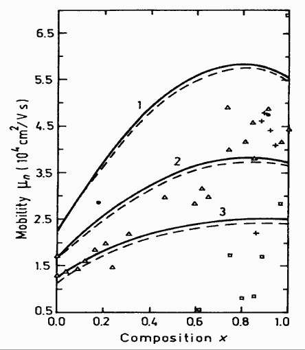
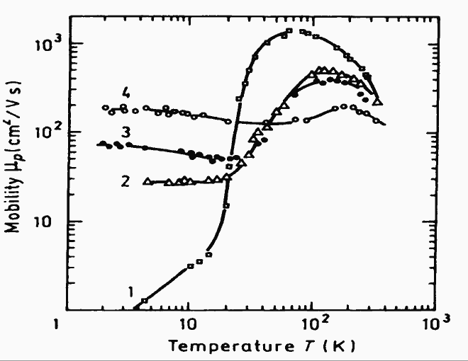
Electron concentration n=5·1016 cm-3 for all curves. Ionized impurity concentration Ni (cm-3): 1. 5·1016; 2. 1.25·1017; 3. 2.5·1017.
Experimental points (triangles full circles, and crosses) are taken from three different papers for n=5·1016 cm-3. (Chattopadhyay et al. (1981))
Squares are experimental results for n=5·1015 cm-3 (Tsukamoto et al. (1990)).
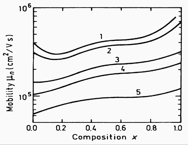
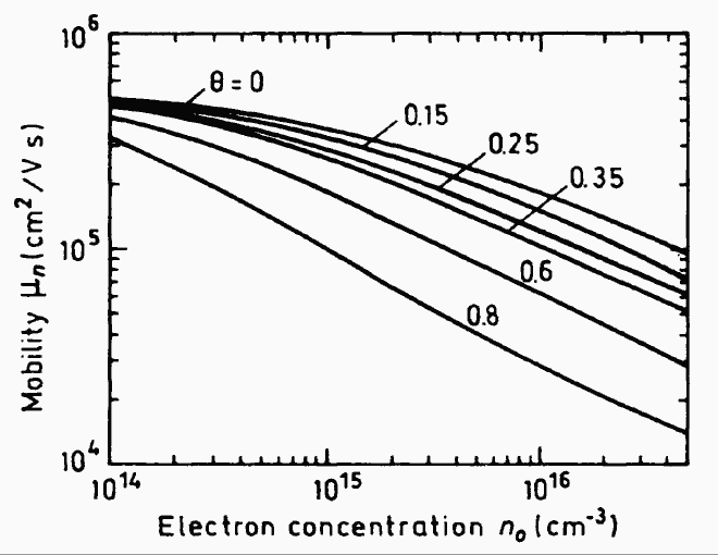
Ionized impurity concentration (cm-3):
1. 5·1014;
2. 1015;
3. 5·1015;
4. 1016;
5. 5·1016;
(Chin et al. (1992)).
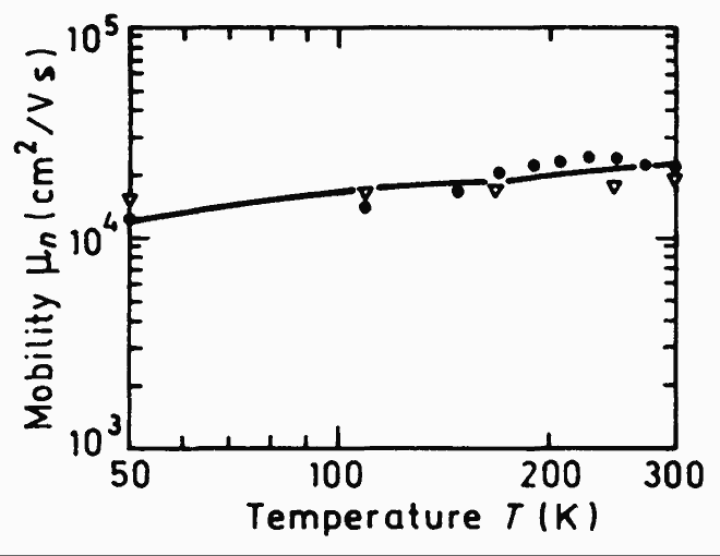
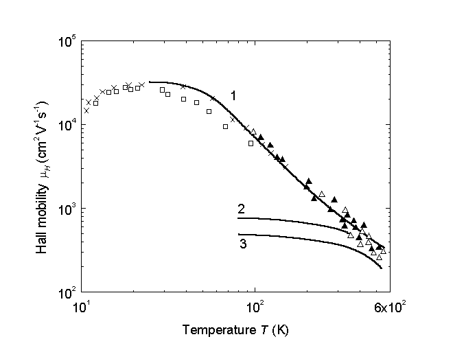
Solid line represents theoretical calculation.
A dislocation density of 1.5·108 cm-2 and a compensation ratio 0.5 are included.
Open triangles: x=0.78
Full circles: x=0.76
n=1017 cm-3
(Egan et al. (1994)).
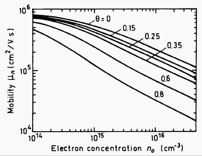
(Chin et al. (1992)).
(Chin et al. (1992)).
Hole concentration at 300K po (cm-3):
1. 5.7·1016;
2. 2.6·1017;
3. 4.2·1017;
4. 1.3·1018.
(Kesamanly et al. (1968)).
po (cm-3):
1. 8·1014;
2. 3.15·1018;
3. 2.5·1019.
(Zimpel et al. (1989) and Filipchenko and Bolshakov (1976)).
1. - 77 K (Filipchenko and Bolshakov (1976)),
2. - 290 K (Willey (1975)).