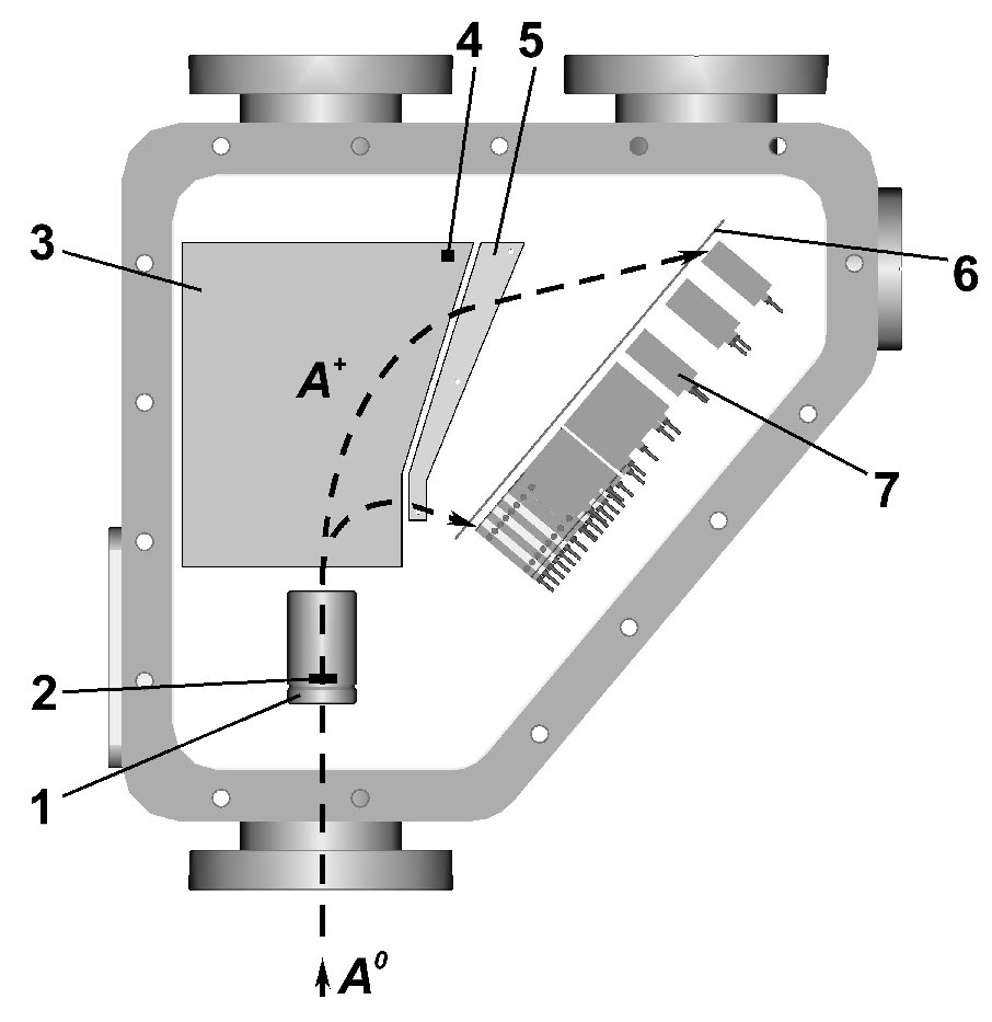
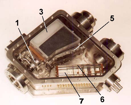
Operating principle A schematic
diagram and a photograph of CNPA-M is shown in Fig.5.2. It is an NPA of E||B scheme.
The accelerator is used for a better collection of secondary ions
scattered in the stripping foil. The NPA dispersion system was specially designed
for the
focusing of ions at the detector area. A shape of magnet poles
and a shape of electrostatic condenser plates were simulated by computer modeling which
included the particle trajectory calculations. The detector unit consists of two channeltron rows coinciding with H and D
mass detection lines.
The Low and High energy modifications of analyzer look very similar
to CNPA-M. The stripping cell of CNPA-L, which uses the gas
stripping method, is located in place of stripping/acceleration unit. CNPA
advantages
CNPA-M as well as CNPA-H has no gas inlet therefore it does not affect the vacuum conditions in
plasma machine.
CNPA uses permanent magnets
which do not
require any power supply.
CNPA has high detection
efficiency.
CNPA
can be (optionally) equipped with
-
built in accelerator and
electrostatic condenser power supply;
-
built in preliminary data
acquisition system.
CNPA is very
compact. Therefore it is easy to arrange a multichord diagnostic
system using the set of such
spectrometers.
|
|
|
|
|
|
|
|
|
Some of the major
components labelled are: (1) stripping/acceleration
unit (or stripping unit for CNPA-L); (2) stripping foil; (3) analysing magnet; (4) Hall probe; (5)
analysing electrostatic condenser; (6) detector mask; (7) detector array; (A0)
atomic flux emitted by plasma; (A+)
secondary ions. |
|